
Assembly Instructions! This is a live file! If you see words change don’t be alarmed, you’re not crazy…. At least not in THAT way.
Additionally some people have requested a printable version, a PDF of this document is available for download here
Intro
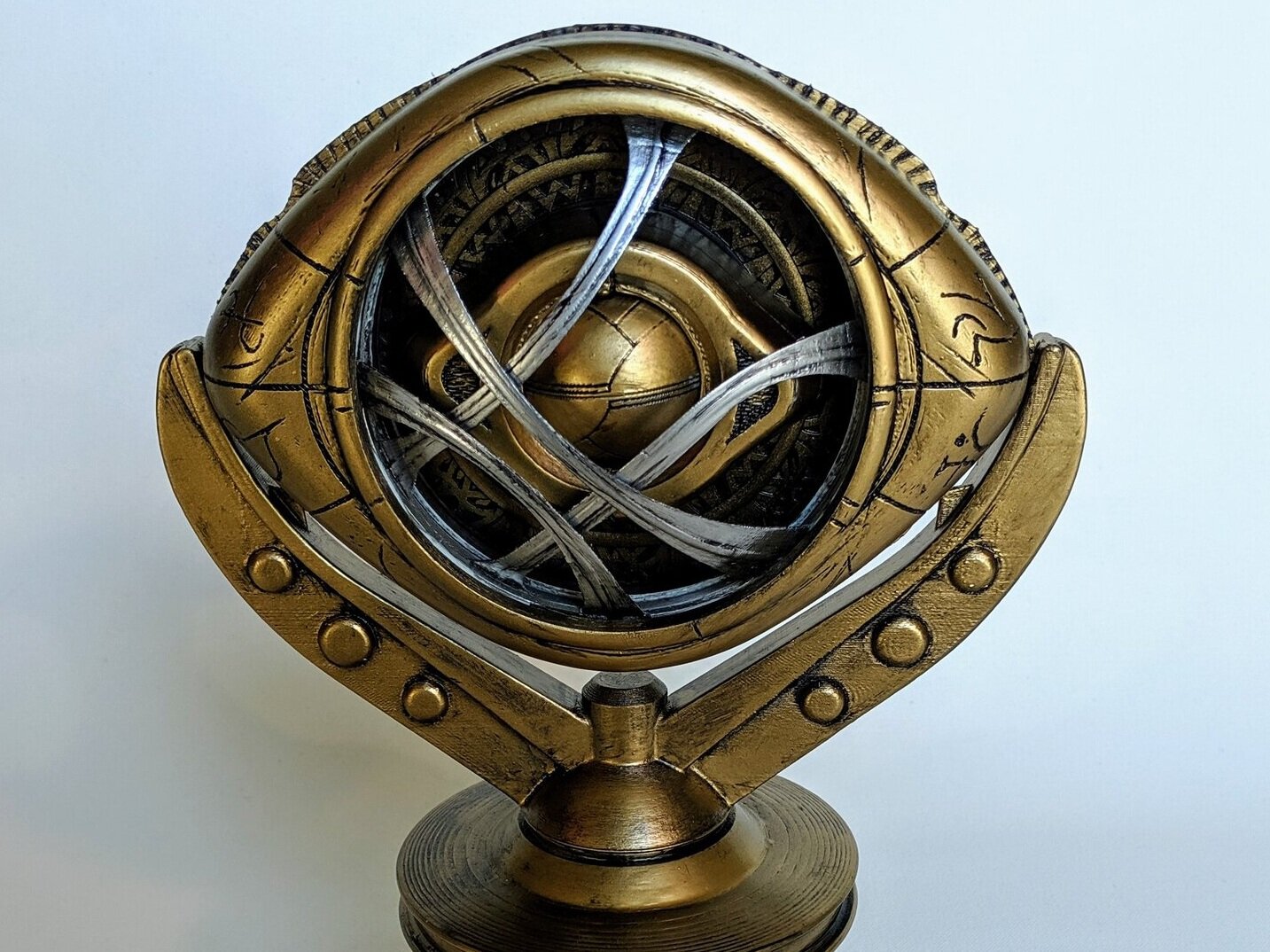
Welcome to the assembly page for the Enza3D Eye of Agamotto kit!
This is a fully 3D printed electromechanical kit. We created it from scratch to emulate the motions seen in the Dr.Strange movie. Unfortunately we were/are bounds by the limits of physics so we had to artistically interpret some of the motion.
This is a HARD build to pull off… if your printer does not print well it will not work. It is definitely worth the time to calibrate your printer well before this. It’s pretty straightforward if you just want a visual display piece, but getting the motions to work takes some time, effort, and sanding.
Parts Overview
Now is a good time to check to make sure you have all of the parts!
You should have the following:
2x | Compound Gear | 3D Printed
2x | Lanyard Hanger | 3D Printed
2x | Reversal Gear | 3D Printed
1x | Accent | 3D Printed
1x | Back Cover | 3D Printed
1x | Carrier Plate Gear | 3D Printed
1x | Carrier Plate Top | 3D Printed
1x | Eye Carrier | 3D Printed
1x | Eye Cover | 3D Printed
1x | Eyelid Bottom | 3D Printed
1x | Eyelid Top | 3D Printed
1x | Front Cover | 3D Printed
1x | Lower Ring | 3D Printed
1x | Main Platform | 3D Printed
1x | Servo Adapter | 3D Printed
1x | Transfer Gear | 3D Printed
1x | Upper Ring | 3D Printed
1x | Resin Infinity Stone | Purchased
1x | Neopixel | Purchased
1x | 9g continuous rotation servo | Purchased
8x | Long M3 Screws | Purchased
8x | Short M3 Screws | Purchased
1x | Elastic Bands | Purchased
1x | Long Shaft | Purchased
3x | Medium Shaft | Purchased
4x | Short Shaft | Purchased
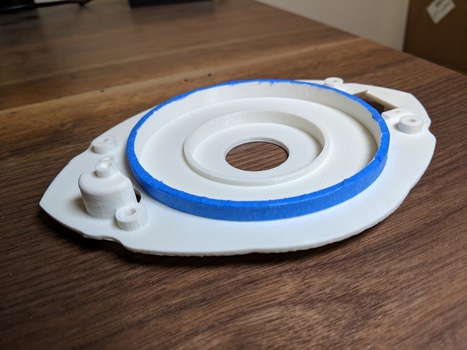
Installing shafts
If you purchased the parts from us directly the holes will be pre drilled to the correct size!
Alright, so you have all the parts, how do they go together?

The first step is to install the shafts into the main platform. To do this you need to enlarge the holes to make room for the shafts. The holes are printed over-sized and you need to drill out the pocket to get the right fit. I drill mine out to 3mm, sometimes a little bit larger.

The 3 medium shafts go in the 3 holes on the top side of the face plate.

The longest shaft goes in the funny shaped pocket on the main plate.

And the remaining two short shafts go into the pockets on the back of the main platform.
You’re almost done, just a few more holes to drill.

At this point I like to open up the shaft holes on the top plate.

As well as the back plate.
Critical Fits
This is a mechanical assembly, that means parts move. Moving parts need to fit together and ideally have very little friction while moving. Here, I'll show you the critical fits that need to be as friction less as possible! A good general rule to follow is if it moves, it needs to move smoothly. If it feels crunchy or too tight, you can sand it with some rough sandpaper and slowly work towards a higher grit (I often went to 600-800). A wax based lubricant is absolutely your friend; White Lightning is my favorite.
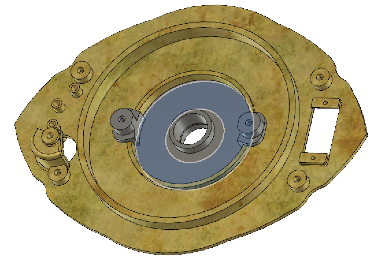


For all of these highlighted surfaces the interface should be as smooth as possible. The servo has to drive all of these surfaces simultaneously, and many of them have a large mechanical advantage due to the gears. If torque at the servo was unlimited it would be easier to ignore the internal friction of the mechanism. If you plan on just making this as a desk ornament and don’t need it to move under its own power you can skip this step! Also if you want to turn the gears manually, your hand has a lot more torque available to it and similarly you can get away with a much “crunchier” assembly.
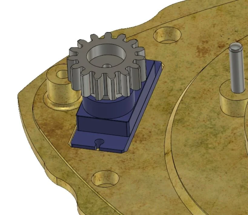
Gear Time!
Alright time to add the gears and test fits. At this point I am going to assume all of your critical surfaces are buttery smooth. The first step here is to drill out the holes of the gears. I use a 3.125 mm reamer to minimize friction in the gear mates while keeping the gears properly aligned and in place. This is a bit overkill and the gears should work just fine drilled out to ~3.3mm if you buy the recommended drill set a 3.3 mm jobber drill comes with it.
https://www.amazon.com/gp/product/B0001P01ZI/ref=oh_aui_search_asin_title?ie=UTF8&psc=1
If you Purchased Parts from us you can again skip the drilling step!
Drill out all of the holes in all of the gears to the nearest size above 3mm you can. Similarly you should drill out the holes of the eyelids while you are at it.


Next you should place all of the gears on the main platform which has the shafts in it from a few sections ago. Try spinning the gears by hand and make sure the feel OK (NO CRUNCHY!)


I generally test the gears by grabbing the longest gear and twisting it. If the assembly binds here, take the time now to chase that friction down. IT WILL NOT WORK IF YOU DON'T DO THIS.
Assembly Time
Next step is to build the Eyelid and cover assembly. Start with Both of the eyelids, and the eye carrier. This part is a little tricky, all 3 parts need to be held in place while a pin is slid into the hole.


The same should be done on both sides and the pins should be pressed until they are flush with the outside of the eyelid parts.

On the side of the eyelids there is a hook feature. This is where an elastic band is wrapped around to act as a return spring, closing the eyes

Next take this eyelid assembly and put it into the carrier plate top.Make sure the eyelid assembly can rotate freely in the carrier plate before moving to the next step.

Next screw the Eye cover to this eyelid assembly using the short screws

Put that assembly away for a moment and place the accent into the main platform

Then place the eyelid assembly into the Main platform assembly

Next up is adding a gear to he back of the assembly we just placed.
Take the Carrier plate Gear and place it on the carrier plate top piece that is not protruding from the back. Screw this in with 4 short screws.
Give that a spin, if it is sticky or doesnt spin nicely, you might have to sand the two touching faces until they move freely. Wax lubricant is your friend!

Next up is to install the servo, it goes in backwards and is screwed in with the included screws.
Next comes the servo adapter, I couldn't get my printer to print the splines even though they are in the model. For me pressing onto the shaft worked fine though.

Next up is to put the ring gears on. They should only go on in one order, make sure to align them as per the movie.

At this point the front cover can go on! Place it on the assembly making sure to align the shaft retainers on the underside of the front cover with the shafts. Screw the cover on from the back with the long screws.

Last thing to do is install the compound gears

And put the back cover on, securing it with long screws, if you would like there are holes at the top of the back cover intended for the lanyard hangers.
The remaining 2 short screws go in the center two holes and they stop the eyeball from rotating.
Now your done!
Electronics
Electronics are a whole different can of worms. Essentially the Neopixel is RGB; you need power and a controller to tell it to crank up the “G” value. Similarly, the servo needs power and a signal to tell it to crank hard left or right to open and close the mechanism.
For the electronics, its part wire wrangling, and part code. Overall the electrical portion of this project is super simple. We turn on an LED and spin a servo. There are dozens if not hundreds of projects that do both of these things. For this project the only unique aspect is the wire routing. The LED for illuminating the eye is held stationary in the assembly. And wires are run through the central shaft to the back plate. At this point one must determine if they are going to power this externally or not. I have always powered it externally, and also brought the electronics outside of the case to allow larger batteries or direct wall power. There is a decent amount of room inside of the back housing. Hiding a digispark in there would not be too much of an issue, what would be problematic though is hiding a large enough battery to rotate the servo with the required torque. In my experience something ~7V is necessary to give enough juice to the servo to overcome internal friction of the mechanism.
With all of that being said, Here is one approach to how one might power this assembly.

For this configuration of the electronics I am using the LED and Servo from our Etsy Kit, a short bit of wire to connect the components, and a adafruit pro trinket as the “brains”. The trinket could be replaced with almost any ATMEGA processor, I did most of the prototyping with a full size Arduino Uno. For this layout I am pulling power from a 9V battery and stepping the voltage down to 7 with a DC-DC converter. The Servo gets this power directly and the LED is powered by the 3V pin on the trinket The LED requires a signal pin to tell it what color to light up, the servo also requires a pin to tell it how it’s going to spin. Since we are using a continuous rotation servo the signal is telling it what direction and how fast to spin instead of explicit location instructions. For the attached code I chose Pin 3 for the LED data signal and Pin 5 for the servo both of which are completely arbitrary. If you have a different controller feel free to edit accordingly.


As for how to snake wires around. The Servo is pretty straightforward, The wires come directly out of it, they have to make their way to the controller, I chose to snake mine back through the back compartment so they could join up with the wires from the LED.
The LED wires have to go behind the Stone “Eye” and stay out of the way of the mechanism. For this I put a channel in the middle of the assembly. The LED should be soldered to wires, the wires should be snaked through this channel and everything should be hot glued in place.
Code
The code is a hot mess… I do not code regularly. Most of this is Adafruit code copy + pasted together. I am certain there is a better way to do this. This is simply how I did it. I encourage anyone who knows better to re write it. I would be happy to post better code here.
// NeoPixel Ring simple sketch (c) 2013 Shae Erisson
// released under the GPLv3 license to match the rest of the AdaFruit NeoPixel library
#include <Adafruit_NeoPixel.h>
#include <Servo.h>
Servo myservo; // create servo object to control a servo
// twelve servo objects can be created on most boards
int pos = 90; // variable to store the servo position
// Which pin on the Arduino is connected to the NeoPixels?
// On a Trinket or Gemma we suggest changing this to 1
#define PIN 2
// How many NeoPixels are attached to the Arduino?
#define NUMPIXELS 1
// When we setup the NeoPixel library, we tell it how many pixels, and which pin to use to send signals.
// Note that for older NeoPixel strips you might need to change the third parameter--see the strandtest
// example for more information on possible values.
Adafruit_NeoPixel pixels = Adafruit_NeoPixel(NUMPIXELS, PIN, NEO_GRB + NEO_KHZ800);
void setup()
{
myservo.attach(5); // attaches the servo on pin 9 to the servo object
pixels.begin(); // This initializes the NeoPixel library.
}
void loop()
{
for(int i=0;i<NUMPIXELS;i++){
// pixels.Color takes RGB values, from 0,0,0 up to 255,255,255
pixels.setPixelColor(i, pixels.Color(0,150,0)); // Moderately bright green color.
pixels.show(); // This sends the updated pixel color to the hardware.
}
myservo.write(180); //Starts the Servo going in the forward direction
delay(1500); // waits 1.5 Seconds for the servo to reach the position
myservo.write(90); // Pauses the motion of the Servo
delay(5000); // waits at that paused position
myservo.write(0); // Spins the Servo in the opposite direction
delay(1500); //waits 1.5 Seconds for the servo to reach the position
myservo.write(90); // Pauses the motion of the Servo
delay(5000); // waits at that paused position
}
Painting
The painting process is pretty straight forward. Basically don’t put paint on bits that slide on other bits. If you follow that guideline you should be fine.
Masking
An easy way to ensure you don’t get paint where you don’t want paint is to cover areas with tape. I used plain old blue painters tape but pretty much anything works here.


Runes & Aging
This step is completely optional, but does do a lot to elevate the final prop!
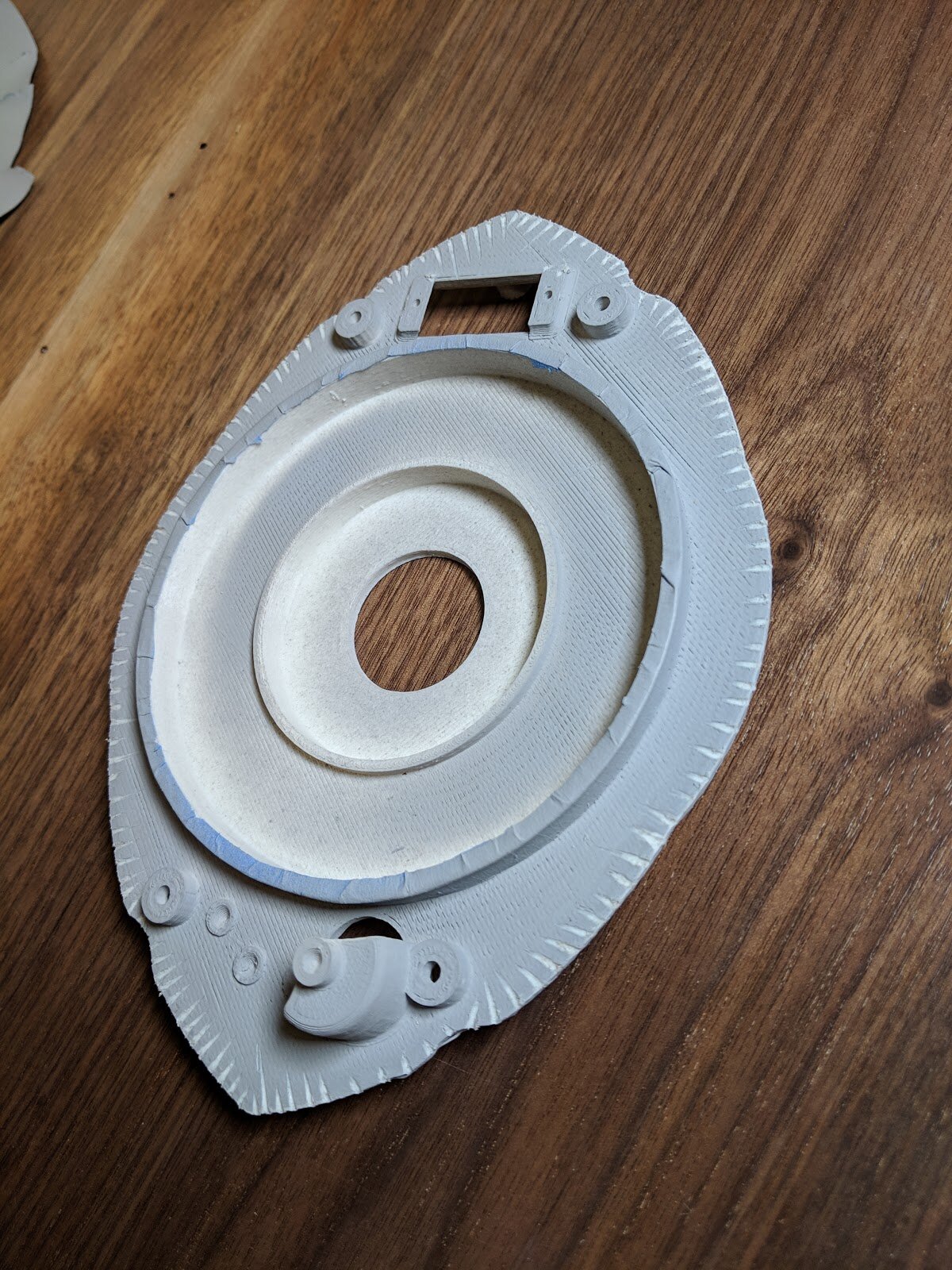
Priming (and Sanding)
Once you tape the parts up you can generally apply a decent amount of primer and/or primer filler depending on how much clean-up your prints need. Once the primer dries, start sanding parts until they look good! This took 4-5 coats of primer filler in rougher regions to smooth out; if a region is looking really rough (voids, holes, apparent layer lines) you can also use Bondo or Green Putty to smooth it out quicker.
For metallic paints, it’s best to go up to a pretty high grit to give the surface the best chance of looking like actual metal (not metal painted plastic). 800 grit is usually enough, but the higher you go, and the more persistent you are, the better your results will be. Sanding a 3D print smooth is not a small undertaking; it’s in this step that 3D printing a prop becomes just as (if not more) labor intensive than making something out of foam.


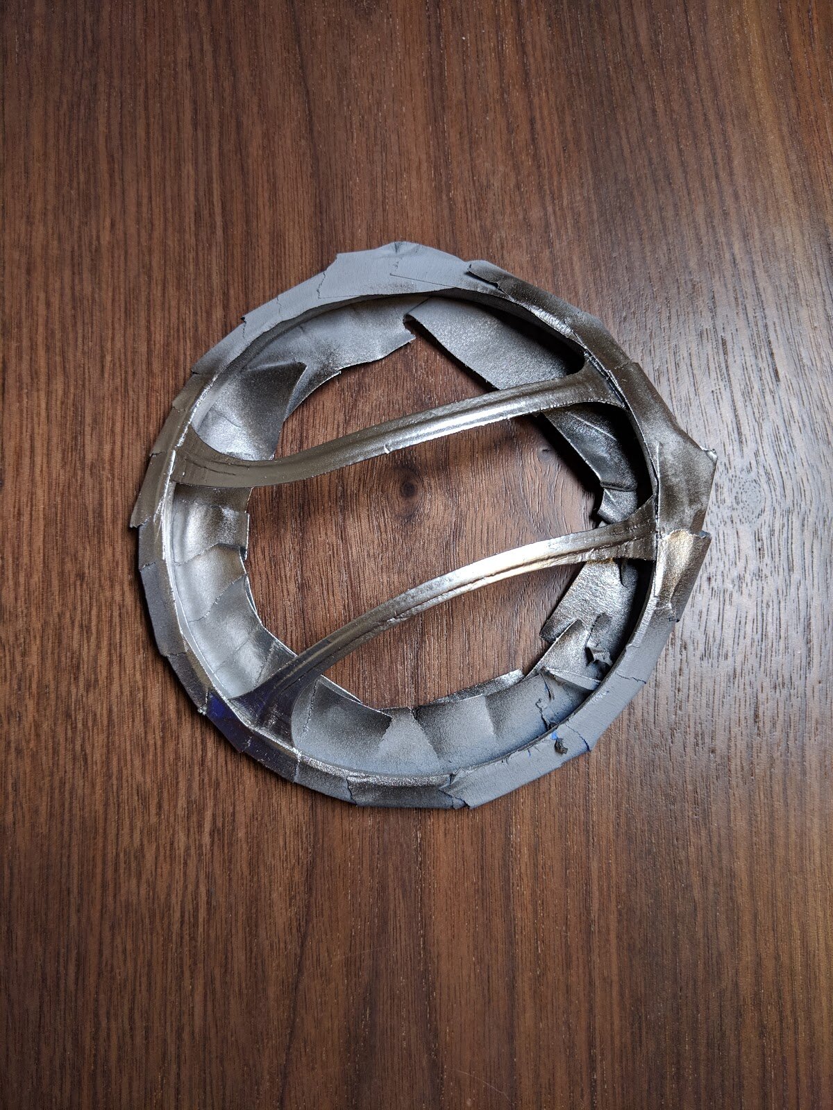
Painting
This part is pretty self explanatory. Once the parts are primed you can paint them. I used some relatively high quality metal flake pigment paints in an air brush. If you go this route, the paints used here were Alclad Pale Gold and Spazstix Mirror Chrome on top of a base layer of Alclad’s Gloss Black. It is really important you sand well, and use the right base for your paint to get a good metallic look! Any and all imperfections will show up with the metallic paints (especially the Chrome) and mixing the wrong paints together often leads to sanding it off and starting again. Which sucks. Don’t do that.
If you don’t have an airbrush, any good quality rattle can paint would do just fine here. Just be sure to use light layers of paint; anything too heavy can seep through the mask or obscure details. I like Montana spray paints, and again, you want to base with some kind of gloss black before applying the metallic paints.


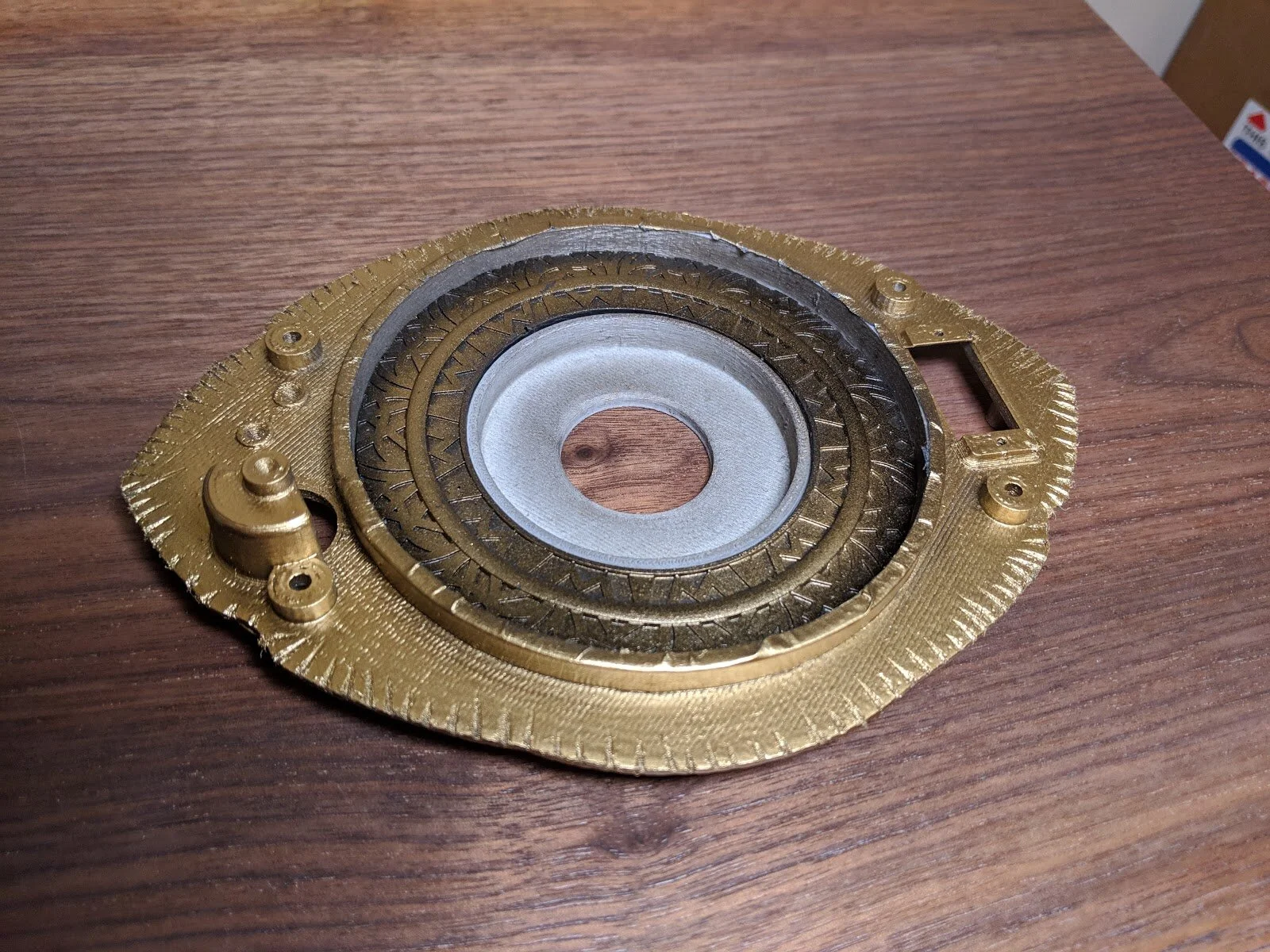

At this point you can call it done, or you can weather it! If you are done, just put it back together once the paint is fully dry.
For weathering, since these are metallic paints, something oil based works much better than standard washes (which are water based). Acrylic washes tend to want to just run off the prop instead of sitting in the crevices, and lead to more of a grease stain look than actual build-up of grime in nooks and crannies. Black or brown (or both) shoe polish is great for this! Just smear it all over the exposed surfaces of the prop, and wipe off with a paper towel. The polish will catch all the details and really highlight them.